
by Floris Wouterlood – June 13, 2023
— Summary
— This post concerns the wiring of a circular 1.28” diagonal 240*240 pixel color display with GCA901A controller to an ESP32 microcontroller. Because the circular display arrived on a five-pin SPI breakout board the ESP32 has a wealth of pins available for all kinds of purposes other than driving displays. This inspired me to construct a bench type of device equipped with an ESP32, a circular display and a row of pin sockets.

figure 1. Wiring diagram: ESP32-WROOM-32 board, 1.28” circular 240*240 SPI GC9A01 TFT display.
Pin mapping
This TFT display breakout board has seven pins (figure 1) of which five serve the SPI interface (CS, DC, SDA, SCL and RST). The two remaining pins are marked VCC and GND. These two are obvious. Note that the display at hand is a 3.3V item. The RST pin is not connected.
Components of the bench
- 1x soldering prototyping board, 8×6 cm, 31×26 holes, double-sided
- 1x ESP32-WROOM-32 microcontroller board, 38-pins
- 1x CG9A01 1,28 inch diameter circular 240*240 pixel TFT display, 5-pin SPI+VCC+GND
- 2x 19-pin socket header (to accommodate an 38-pin ESP32
- 1×7 pin socket to accommodate the display
- 1x 4-pin and 1×17 pin socket header for bench purposes
- 2x 4-pin pin headers for bench purposes (3V3, GND)
- Audio cassette box
- wire
- 3x nylon spacer with screw and nut to fasten the board onto the cassette box
Pin connectivity table
| GC9A01 display | ESP32 pin |
| RST | — |
| CS | D4 |
| DC | D2 |
| SDA | D23 |
| SCL | D18 |
| GND | GND |
| VCC | 3V3 |
Wiring
We are using conventional pin mapping: SCL (clock) and SDA (data, on other displays named MOSI) connect to pins D18 and D23 of the ESP32, respectively. Wiring is as follows (figs. 2,3).
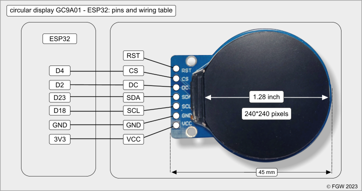
figure 2. Pin connectivity ESP32-WROOM-32 board, 1.28” circular 240*240 SPI GC9A01 TFT display.
Building a bench
The ESP32 comes with an impressive set of pins. A wired, soldered device equipped with a pin socket that connects to the free pins of the ESP32 creates an attractive bench. In my design a vertical strip on the left of the ESP32 / display carries a pin socket plus at its base one four-pin GND socket and a four-pin 3V header. All pins to supply external sensors with power and data communication are now on the front of the bench device, easily available for experimentation (figures 3,4). The sockets are stickered with their respective ESP pin connections.

figure 3. Outlay and wiring scheme for the ESP32 / circular display bench. The wiring between the extra pin sockets and the free ESP32 pins is not included.
Downloadable sketch
The ZIP file: WROOM32_GC9A01.zip contains the following:
- WROOM32_GC9A01-Adafruit_GFX.ino – needs the Adafruit_GFX.h and the Adafruit_GC9A01A.h libraries
- WROOM32_GC9A01_TFT_eSPI.ino – needs Bodmer’s <TFT_eSPI.h> library and a user setup file that contains settings that directs the compiler to do its job properly with this combination of ESP32 and display.
TFT_eSPI User_Setup_Select file
Download or install in your Arduino IDE the library TFT_eSPI. After installation you will see in your snap-arduino-libraries folder a main folder named TFT_eSPI. That folder hosts a subdirectory named User_Setups. The file below is an adaptation of setup file #46 in that subdirectory.
My setup file carries the name <Setup_ID_46_ESP32_GC9A01.h>
A line should be added in User_Setup_Select.h, and uncommented.
#include <User_Setups/ Setup_ID_46_ESP32_GC9A01.h> // your comment
Content of User_Setups/ Setup_ID_46_ESP32_GC9A01.h is the followig:


figure 4. The completed bench built around an ESP32 and a GC9A01 circular display. The microcontroller is running the graphics test attached to the AdafruitGC9A01 library.

Leave a comment