
by Floris Wouterlood — March 2, 2024–
Summary
— An incredibly small, yet powerful and handy microcontroller board is the XIAO-ESP32-C3 made by seeed studio. We wire this board here to a 3.2” diagonal, 320*240 pixel TFT display with ILI9341 controller – SPI connectivity interface and get (expected) nice results.
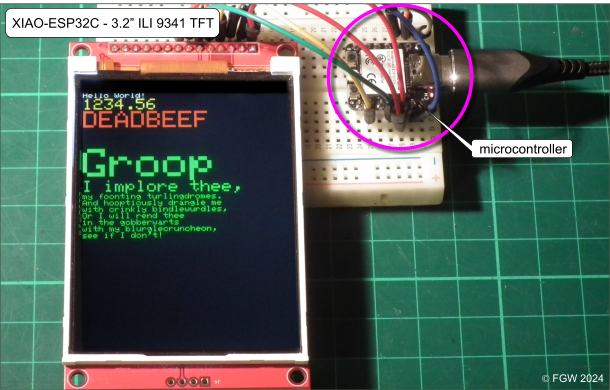
figure 1. Wiring diagram: XIAO-ESP32-C3 board and a 320*240, 3.2” diagonal SPI TFT display with ILI9341 controller. The processor is running the Adafruit_GFX graphics demo.
Microcontroller
The XIAO-ESP32-C3 is a 14-pin board with on it a ESP32-C3 single-core, 32-bit, RISC-V-based MCU made by Espressif Systems, with 400 Kb of SRAM memory, The processor runs at 160 MHz. On board is 2.4 GHz Wi-Fi. Bluetooth is supported to connect, for instance, with Android devices. The board features for this purpose a connector on which an additional, external wifi antenna can be mounted. The manufacturer claims on its website that the ESP32-C3 is designed “for simple and secure connectivity applications” (https://www.espressif.com/en/news/ESP32_C3). According to its specs the ESP32-C3 has 22 programmable general purpose in-output pins, and separate 3.3V and 5V pins to supply power to external devices such as displays. Pinout schemes can be found in the cloud. Connection to a computer is through a usb-c connector. The board can be programmed according to Arduino convention (use in Board Manager = XIAO_ESP32C3 from the supported ESP32 boards list. A peculiarity of programming the XIAO with the Arduino IDE is that pins must be indicated with a ‘D’ prefix.
Pin mapping
The TFT display breakout board that I used is a 3.2 inch diagonal display that has 14 pins (figure 1). Five of these support the SPI interface (SCK, SDI, RESET, D/C and CS). Pins labeled marked VCC, GND and LED serve the breakout’s power needs while the remaining support memory card reader functionality. The VCC and GND pins are obvious. LED is the backlight pin which is essential with this display. It needs to be connected with the 3.3V rail. If this pin is not supplied with power the display will not seem to work (it actually will work but you won’t see anything because the screen remains unilluminated).
Pin connectivity table
| 240*320 display ILI9341 | XIAO-ESP32-C3 pin |
| VCC | 3V3 or 5V |
| GND | GND |
| CS | D0 |
| RST | D2 |
| DC | D1 |
| SDI | D10 |
| SCK | D8 |
| LED | 3V3 |
Wiring
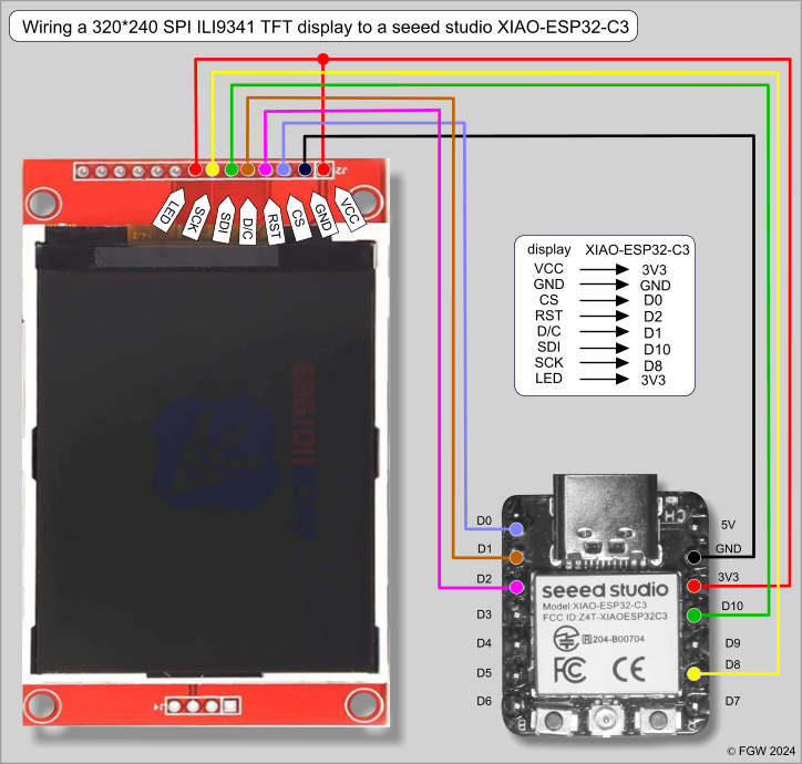
figure 2. Wiring diagram for a 320*240 SPI TFT display with ILI9341 controller and a seeed studio XIAO-ESP32-C3.
We are using conventional hardware pin mapping: SCK (clock) and SDI (data, on other displays named SDA, or MOSI) connect to pins D8 and D10 of the ESP32, respectively. Chip Select (CS) is wired to pin D0. These are hardware SPI pins. DC is connected to pin D1 and RST to pin D2. The backlight LED needs 3.3V and for that matter is wired to the 3V3 pin of the ESP32. The wiring diagram is shown in figure 2.
Libraries
Both the Adafruit_ILI9341.h (hand in hand with Adafruit_GFX.h) and Bodmer’s TFT_eSPI .h library support the ILI9341 controller. I got best results with the XIAO-ESP-32C with sketches compiled using the TFT_eSPI.h library.
Adafruit_ILI9341 library
Adafruit libraries typically require a ‘constructor’ statement in the sketch. This constructor identifies to the library the particular controller chip and the ‘variable’ pins, i.e., the ones that are used for control lines CS and DC. Here the constructor reads ‘Adafruit_ILI9341 tft = Adafruit_ILI9341 (D0, D1);’. In the declaration area the following should be present:
#include “SPI.h”
#include “Adafruit_GFX.h”
#include “Adafruit_ILI9341.h”
#define TFT_DC D1
#define TFT_CS D0
#define TFT_RST D2
Adafruit_ILI9341 tft = Adafruit_ILI9341 (TFT_CS, TFT_DC);
TFT_eSPI library with its User_Setup_Select file
Bodmer’s TFT_eSPI library is a well-equipped library. it supports a variety of microcontrollers and graphical display chips. While a ‘constructor’ is necessary you won’t see it because the pin definitions reside in a separate, editable file in a separate directory: a specific User_Setup.h file. This particular file is called in another library file named User_Setup_Select.h. Both library files are ASCII files editable with a standard text-only editor such as Notepad in the Windows environment and Gedit in Linux.
First the User_Setup_Select.h file because its contents calls data from the next file (the User_Setup.h). In User_Setup_Select.h, the following, uncommented line must be entered:
#include <User_Setups/ Setup_XIAO_ESP32C3_ILI9341.h> // your comment
while all #includes to other User_Setups must be ‘imprisoned’ by comment slashes. Check this!
Next the actual User_setup.h file.
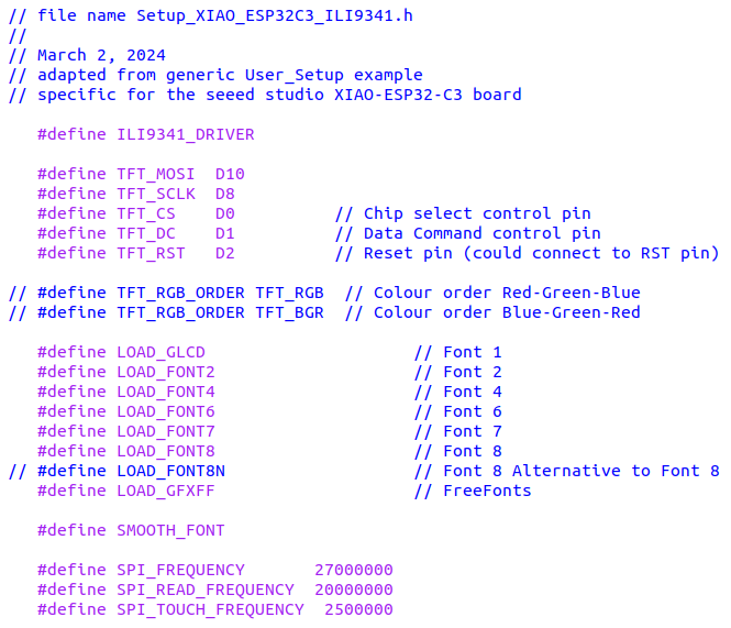
My specific User_Setup file for this combination of microprocessor and TFT breakout carries the name <Setup_XIAO_ESP32C3_ILI9341.h>. This files is an adaptation of the generic User_Setup.h file that is supplied as part of this TFT_eSPI library ‘suite’,
Content of Setup_XIAO_ESP32C3_ILI9341.h (to be located in the User_Setups folder) is the following. For the sake of clarity I have removed most comments:
Wiring a DS18B20 temperature sensor
How a DS18B20 temperature sensor works and how to connect it, is described in a previous post *. Here the DS18B20’s data pin is wired to the XIAO’s pin D5.
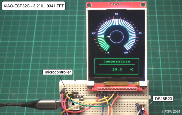
figure 3. XIAO ESP32-C3 wired to a 320*240 SPI TFT display with ILI9341 controller, with pin D5 wired to a DS18B20 temperature sensor. The sketch is downloadable.
Result
The seed XIAO-ESP32-C3 is a minuscule board with impressive processing power that perfectly matches this TFT display. Graphics are fast. The benchmark results of Adafruits ‘graphicstest’ example are the following (compiled assisted with the Adafruit_GFX.h and Adafruit_ILI9341.h libraries):
| Benchmark | Time (microseconds) |
| Screen fill | 217043 |
| Text | 31059 |
| Lines | 319066 |
| Horiz/Vert Lines | 19579 |
| Rectangles (outline) | 13135 |
| Rectangles (filled) | 451107 |
| Circles (filled) | 86492 |
| Circles (outline) | 140875 |
| Triangles (outline) | 70039 |
| Triangles (filled) | 174775 |
| Rounded rects (outline) | 57346 |
| Rounded rects (filled) | 461292 |
| Done! |
The same ‘graphicstest’, but now run after compilation with the TFT_eSPI.h library, are the following:
| Benchmark | Time (microseconds) |
| Screen fill | 236476 |
| Text | 19365 |
| Lines | 114427 |
| Horiz/Vert Lines | 21012 |
| Rectangles (outline) | 13313 |
| Rectangles (filled) | 491175 |
| Circles (filled) | 73794 |
| Circles (outline) | 42558 |
| Triangles (outline) | 27425 |
| Triangles (filled) | 173338 |
| Rounded rects (outline) | 24603 |
| Rounded rects (filled) | 496910 |
| Done! |
Discussion
The seeed XIAO-ESP32-C3 mini board is capable of supporting great graphics on SPI TFT displays. The display requires 5 pins while the little microcontroller board has 11 physically addressable pins. This means that with this display 6 input/output pins are available to connect with external sensors, actuators and led drivers. A disadvantage is that there is no antenna on board. Wifi or Bluetooth need an external antenna. Another disadvantage is that the port is a usb-c post which is poorly supported by the Arduino IDE. On Linux systems the port is named dev/tty/ACM0(ESP32S3DevModule. During experimentation this port is easily lost and, unfortunately, hard to recover. When the port is lost, the dev/tty/ACM0(ESP32S3DevModule port can be restored by disconnecting the usb-c followed reconnecting and uploading a sketch while simultaneously pressing the B (boot) and R (reset) buttons on the board, a nearly impossible manipulation because it requires three hands. Stable usb-c support under Linux would be handy.
Downloadable sketch
For this project I have created the sketch ‘XIAO-ESP32-C3_ILI9341_DS18B20.ino’ that is the display of a temperature sensor attached to pin D5 (figure 3). It should be mentioned that the engine of Bodmer’s rainbow scale gauge is embedded in the sketch to enhance visual display.
Download ‘XIAO-ESP32-C3_ILI9341_DS18B20 .ino ’ (packed as ZIP file)
References
**** The DS18B20 temperature sensor – implementation with an Arduino. TheSolarUniverse, August 17, 2017.
