
by Floris Wouterlood – The Netherlands – January 1, 2023 —
Summary —
We describe here the pin-to-pin connectivity of an ESP8266 microcontroller board with an 1.8 inch diagonal 128*160 pixel TFT display with ST7735S controller and a SPI interface.
Introduction —
The advantage of combining an ESP8266 microcontroller board and a TFT display does not need much comment. The ESP8266, manufactured by Espressif Systems, is a low-cost, 3.3V solution perfect for all sorts of Internet of Things projects. Compared to the common Arduinos the ESP8266 has higher speed, more memory and the fantastic feature of on-board wifi. TFT displays respond fast and, apart from being economical, they support 16-bit color. Here we wire an ESP8266 NodeMCU and a popular display: a single-row 8-pin header, 128*160 TFT display breakout with ST7735S controller. The SPI interface uses here five of the available pins on the TFT breakout board: SCK, SDA, A0, RESET and CS. The remaning pins are labeled VCC, GND and LED. In a previous project I have wired this display to an Arduino Nano microcontroller board. As the ESP8266 reponds much faster than an Arduino Nano its combination with a 16-bit color TFT is very attractive. Think of applications where a small visual device graphically portrays processes going on in the main microprocessor, or of animations and sprites.
Pin-to-pin wiring
Figure 1 illustrates pin wiring of the 128*160 TFT with an ESP8266 NodeMCU. In a table:
| NodeMCU pin | 128*160 TFT | on other TFT breakouts called |
| 3V | VCC | VCC |
| GND | GND | GND |
| D8 | CS | CS |
| D4 | RESET | RST |
| D3 | A0 | D/C, DC |
| D7 | SDA | MOSI, DATA |
| D5 | SCK | CLK, Clock |
| 3V | LED |

figure 1.Wiring diagram: 1.8 inch diagonal 128*160 ST7735 TFT display and an ESP8266 NodeMCU board.
Libraries and pins
I have used Bodmer’s TFT_eSPI.h library with a User_Setup file modified to suit the combination of ESP8266 and the ST7735S controller. TFT_eSPI provides perfect support for this display. TFT_eSPI does follow its own conventions: inside the Arduino sketch is a universal call to the TFT_eSPI.h library. TFT_eSPI checks wjether there is a line in an external User_Setup_Select.h file that points to a user modified text file associated with the used microcontroller board and the specific display. One could say that the ‘constructor’ such as used in other scripts to define the display at hand is positioned external to the sketch.
In my TFT_eSPI environment the User_Setup_Select.h file contains an uncommented line,
include <User_Setups/Setup_FW_ESP8266_ST7735_TFT_012_OK.h>
and here is the contents of this particular user setup:
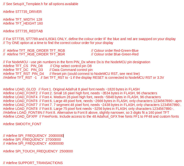
One can see the ‘constructor’, notably in the lines that #define TFT_CS, TFT_DC and TFT_RST.
The contents of this file is the same as Setup2_ST7735.h supplied standard in the folder named User_Setups in the TFT_eSPI.h library ‘suite’ . This folder is extremely valuable since it contains a wealth of examples – I simply duplicated the file Setup2_ST7735.h
to suit my own purposes, referring to the TFT display catalogued in my own bookkeeping as TFT_012: an 128*60 – 8 pins 1.9 inch TFT with ST7735 controller.
An alternative library is Adafruit_ST7735.h made by Adafruit Industries. The latter library also gives perfect support. A sketch that uses the Adafruit library needs a ‘constructor’ instruction that specify which pins on the microcontroller board are used for the chip select (CS), data command (D/C) and reset (RST) functions. Here, CS is wired to pin D8 of the ESP8266, A0 to pin D3 and RESET to pin D4. The constructor in the Adafruit sketch henceforth is:
Adafruit_ST7735.tft = Adafruit_ST7735 (D8, D3, D4);
At work
The 1.8 inch 128*160 TFT was originally planned to star in another project. In the current project I took the example ‘Clock’ from the TFT_eSPI library examples. Clock uses compilation time as the start time for the clock. It will use that time again if power to the microcontroller-TFT assembly is interrupted and restored. One needs a battery-powered real time clock module to keep track of real time, or the wifi option of the ESP8266 can be used to connect to the Internet and pick up time from a time server.
Downloadable sketches:
There are two sketches:
- ESP8266_ST7735_Bodmers_clock.ino, a real time analog clock example adapted from Bodmer’s TFT_eSPi library examples (display visible in figure 2).
- ESP8266_ST7735_Adafruit_demo.ini: the well known Adafruit repertoire of graphic tests that illustrate the performance of the display.
Sketches are packed in a ZIP file: ESP8266_ST7735_BodmerClock_Adafruit_demos.zip
References
* Arduino and 160×128 TFT display with ST7735S controller – TheSolarUniverse, August 4, 2017.

Where did you get your 128 x 160 ST7735 display?
LikeLike
Aliexpress
LikeLike