
by Floris Wouterlood – The Netherlands – August 11, 2017
Summary
Graphic 128×64 LCD displays are based on (monochrome) LCD technology, yet they offer interesting graphical capabilities because every pixel is individually addressable. These displays are more complicated to program than the ‘common’ 16×2 or 20×4 LCD displays that present two or four rows of fixed character positions. The payoff is presentation with considerable flexibility thanks to the existence of built-in characters and, in software for the Arduino, an extensive u8g graphics library, i.e., the same library that supports display of graphics on OLED displays. Here we discuss the wiring of a ST7920 based 128×64 graphical 12864B LCD breakout display. This display is used to present data collected with a Dallas DS18B20 temperature sensor and a DHT11 relative humidity sensor.
Introduction
One of the solutions to display data collected with sensors attached to an Arduino microcontroller board is via a graphic 128×64 LCD display (Figure 1).Because the pixels are neatly arranged in 128 columns, 64 rows where every individual pixel is addressable these displays offer graphic capabilities where even images can be displayed (of course in monochrome). In this paper we discuss a very common type of 128×64 LCD display breakout based on the ST7920 controller. In spite of the impressive 20 pins that decorate this board only three pins of an Arduino are essential to make the display work, that is: in SPI mode. This modest ‘pin requirement’ makes the ST7920 display attractive for use in Arduino projects where other pins need to be reserved for all kinds of peripheral devices and actions. The screens are in vertical direction twice as big as 20×4 LCD displays so they offer good readability. The u8g library written by Oliver Kraus (‘Olikraus’) offers a selection of graphic functions, special characters and text fonts which makes the use of this kind of display extra attractive.
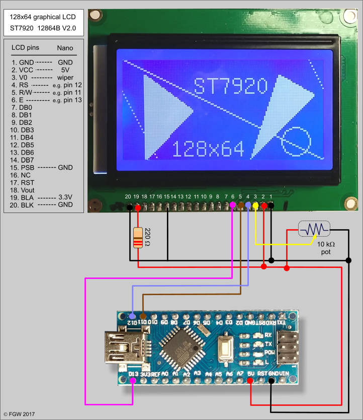
Figure 1: Wiring of a graphic 128×64 LCD display, in SPI mode. Only 3 digital pins of the Arduino are required to get output on the display: pins supporting the functions RS, R/W and E. Here, RS is wired to the Nano’s pin 12, R/W to pin 11 and E to pin 13. These pins need to be declared in the display constructor part of the sketch. The display shows a few of the graphical features offered by the u8g library: triangles, lines, circles, text.
Electronics and supplies
1x Arduino Nano microcontroller board, breadboard, Dupont jumper wires, 128×64 ST 7920 based LCD display breakout board, 1x 10 kΩ potentiometer, 1x 220 Ω resistor. Additional: 1x DHT11 temperature/ relative humidity sensor, 1x Dallas DS18B20 temperature sensor , 1 x 10kΩ resistor, 1x 4.7 k10kΩ resistor.
Wiring
The LCD display breakout board has 20 pins for connectivity, labeled GND, VCC, V0, RS, R/W, E, DB0, DB1, DB2, DB3, DB4, DB5, DB6, DB7, PSB, NC, RST, VOUT, BLA and BLK.
Figure 1 shows the basic connectivity via the SPI interface (SPI stands for Serial Peripheral Interface). GND is wired to GND of the Arduino, 5V to 5V, V0 to the wiper of a 10kΩ potentiometer (this is to adapt the contrast between characters or graphics of the LCD against the background), RS to pin 12, R/W to pin 11 and E to pin 13. The DB0 through DB7 pins of the breakout board need to be connected only if parallel mode is considered. PSB is connected to ground, while BLA needs 3.3V (background LED light of the LCD display) and BLK needs connection to GND. BLA can be connected to the 5V pin of the Arduino with a 220Ω resistor in series to reduce the voltage, or it can be connected directly to the 3.3V pin of the Arduino.
Confusion in nomenclature
While SPI protocols work with pins marked MISO, MOSI, CLK and CS, the ST7920 breakout board has completely different pin designations while it supports the SPI protocol. MISO and MOSI are necessary for master/slave mode and do not matter in the present construction. CLK (clock) and CS (chip select) are necessary and so are the data pin (R/W) and the pin marked PSB (the latter needs to be connected to GND – pin set continuously LOW to inform the display’s controller chip that it should work in serial mode (PSB HIGH means parallel mode).
Summarized: SPI’s CLK is supported by pin ‘E’ on the display breakout board, data is supported by pin ‘R/W’ and Chip Select by pin ‘CS’. PSB should be connected to GND and the wires to GND, VCC, VD, BLA and BLK supply power to the display breakout and regulate background light and contrast of pixels versus background.
Flexibility of pin selection
SPI is not hardware mapped, i.e., the protocol does not require specific pins of the Arduino. However, the pins of the Arduino used to connect CLK, data and CS need to be declared in the display constructor (see below). Use of different pins is allowed as long as they are correctly declared in the display constructor, e.g. pins 2, 3 and 4.
.
Sensors and their connectivity
A Dallas DS18B20 is an accurate temperature sensor that has three wires: 5V, GND and DATA. The DATA wire can be connected to an Arduino pin of choice; in this example pin 6 (Figure 2). A DHT 11 has four pins of which (seen from the front, from left to right, Fig. 2) the first pin needs to be connected with 5V, the second is DATA, in this example connected to pin 8 of the Arduino, the third pin is not connected while the fourth pin needs GND. While a DHT provides both relative humidity and temperature, the accuracy of a Dallas DS18B20 is much better. Apart from that this article was written to show that readings from two completely different sensors can easily be displayed on this LCD display. Note the pull up resistors that are necessary to get ‘clean’ data signals from the sensors.

Figure 2: Wiring of the LCD display breakout board is the same as in Figure 1, but now sensors have been connected to the Arduino: a Dallas DS18B20 – indicated with the pink circle, and a DHT 11 temperature/relative humidity sensor. Both sensors require for data relay only one pin of the Arduino (and of course 5V and GND). Note that all data: temperature and humidity of the DHT is transmitted via the DATA wire (colored white). Both sensors need a pull-up resistor: the DS18B20 won’t function without a 4.7 kΩ resistor while the DHT11 needs a 10 kΩ pull-up resistor
Sketch – notes
The sketch that provide all instructions to the Arduino makes use of the u8g library written by Oliver Kraus (nickname on the Arduino forum ‘Olikraus’). As the sketch (named ‘LCD_128x64_ST7920_DS18B20_DHT11’ can be downloaded from the website I discuss here the outline of the sketch and in more detail two tricky parts.
Libraries
necessary are:
U8glib.h — graphic display control library,
OneWire.h — single bus protocol for data transfer of the DS18B20 sensor
DallasTemperature.h — extra library with DS18B20 instructions.
DHT.h — library with DHT instructions
Declared variables
Both character strings, temp_string [5] and hum_string [5] are character arrays necessary in the sketch because of the peculiarity that the u8glib library does not offer instructions to display the values stored in variables. This library was apparently specifically written to display graphics. A trick to circumvent this limitation is to convert variables into character strings and display these on the LCD display. Values for temperature and humidity should be stored in float variables (because ‘floats’ support decimal notation).
Display constructor
Please note that this line contains the pin designations for CLK, R/W and CS. The line U8GLIB_ST7920_128X64 u8g (13, 11, 12, U8G_PIN_NONE); implies that CLK (pin marked E on the display breakout is connected to pin 13 of the Arduino, pin marked R/W on the display breakout to pin 11 of the Arduino, and pin marked RS on the display breakout with pin 12 of the Arduino.
DS18B20 device address
DeviceAddress: Every individual DS18B20 sensor has its own 8-byte identity, the Device Address. Via the one-wire protocol a sensor with a particular device address receives a call to release its data (temperature reading). This makes it possible to read multiple sensors via only one wire an one pin of the Arduino.
The device address of a DS18B20 can be found via a sketch ‘DS18B20_address_finder.ino’ – downloadable from the website. You may locate this sketch or a similar one on the internet.
Void loop() and void draw()
The essence of the Olikraus approach of displaying graphic matter via an Arduino with its very limited memory on a multipixel device like the ST7920 128×64 LCD display is to work with a cache whose contents is printed in the appropriate position in the 128×64 pixel space. In analogy with a journal publisher who works with two departments: Editorial and Print, a screen is constructed in void draw (), just like pages for a journal are made up by editorial staff in the publisher’s Editorial Department. When the screen is ready it is sent via the cache (the call ‘nextPage ()’ ) to the Print Department. This procedure is essential for saving precious memory.
All instructions for calculations and actions must therefore be located within the ‘Draw()’ subroutine.
Conversion of float variable to character string
The numerical value of the temperature measured by the DS18B20 is stored in the float variable ‘tempC’, which holds for instance a value 24.2 degrees centigrade. This numerical value is converted into four characters: ‘2’ – ‘4’ – ‘.’ and ‘2’, and stored in the character string ‘temp_string” via the instruction:
dtostrf(tempC, 3, 1, temp_string);
Immediately afterwards this string is drawn to screen beginning on pixel 33,37 with the instruction: u8g.drawStr(33,27, temp_string;
and the line is finished by adding: u8g.drawStr(70,27, “*C”);
The same is done for the value of the relative humidity as reported by the DHT11.
Sketches
DS18B20_address_finder.zip — sketch to find the device address of any Dallas DS18B20 sensor. Should be separately run.
LCD_128x64_ST7920_DS18B20_DHT11.zip — sketch that reads temperature and humidity from the respective sensors and displays on screen, as shown in Figure 2.

Hi
Was looking for the source of this project of you.
But could not download it….
So please sent a copy to me
Greetings
H.T. Gerbenzon
LikeLike
Hi HTG – the link has been restored today (22 january, 2018). Success!
LikeLike
link updated today (January 22, 2018). Should work
LikeLike
the file “LCD_128x64_ST7920_DS18B20_DHT11.zip” is down / not available, can you check this and upload elsewhere maybe github.com or so the sketch?
LikeLike
Hi Tobias,
I checked the link (it is a redirect to the ‘Arduino Corner’ on my Dutch website on solar panels. The file should be downloadable now. heck it out and have fun.
LikeLike
hello i think he must miss a command line in the program. I did the program and I have both rectangles, but no temperature, no humidity.
you have an idea in advance thank you.
LikeLike
….. err… did you wire it up with a DHT11 and a DS18B20?
LikeLike
YES
both, and I have both rectangles, but empty without temperature or humidity
Usually if there is a problem of sensor it has nevertheless written temperature or humidity;
LikeLike
Electronics and supplies Column, it’s nano board , not uno board
LikeLike
Hi Dick, thank you. Uno and Nano are interchangeable, so there would not be any ‘damage’, fortunately. Nevertheless I followed your suggestion. Uno is from now on Nano!
LikeLike
I wondered why you didn’t power the back-light via the 3.3V pad on the Nano, is there a reason? Thanks for the article and the code it is sort of working on my Chinese knock-offs. I shall persevere.
LikeLike
Hi BK.
Sure, it would be possible to supply 3.3V to the backlight pin of the LCD. In the ESP8266 (Wemos D1) version I did that (https://thesolaruniverse.wordpress.com/2020/06/04/connecting-a-wemos-d1-mini-and-a-12864-liquid-crystal-display/). Bo both versions (Nano, ESP8266) now continuously run a Dino animation while I am working on my computer.
LikeLike
hi
god job ! but is it possibile to update the files links please its all down tank a lot
LikeLike
Hi Kidd, the links work perfectly from here. Maybe it is a browser problem – I recommend trying another browser.
LikeLike
Floris – A quick note to express my thanks. Your article is very thorough and so well written. You have a deep understanding of the Nano and the ST7920 display and it helped me a lot. Kind regards.
LikeLike
hi Donal, thanks! 🙂
LikeLike
hi, i cant find the scetch download,
LikeLike
Hi Floris,
Thanks for all your explanations. Helps a lot.
check out your download links. Can not download the zip files.
Regards
Corne
LikeLike
Hi Corne,
I suggest to click on the file names and ignore the warnings from your browser. If you are afraid of clicking, sendd me a note, Floris
LikeLike
Very good project, that I`m still looking for long time, but only prob is I can`t download the files, can you provide it for me, please.
LikeLike
Hi V,
This post is an old hand! 2017, such a long time ago. The sketch is still available on the server at zonnepanelen.wouterlood.com/arduinostuff and the link works properly, here from the SolarUniverse site. However, your anti-virus, anti spam- or security settings may block you from downloading. Please review the security settings in your browser. My Arduino site on WordPress is 100% reliable and trustworthy. If things do not work, spell out your email address and I will send you a copy through email.
regards Photoncatcher
LikeLike